
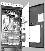
Click the Blue Balloon to view additional information
1
2
3
4
5
6
7
Power Supply (Dryer Panel)
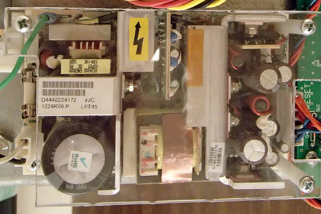
The Power Supply for the Dryer Panel control circuitry is a multiple-output regulated switching supply. Its outputs are +15VDC, -15VDC, and +5VDC.
- +15VDC is used to power the QUANTUM® Controller if it is located on the Inner Door;
- +5VDC is used to power the Slave CPU Board for processor control.
Adjustment of the output is controlled by the small potentiometer located on the edge of the circuit board (see layout below). Adjust for +5.05VDC to +5.15VDC. If the output is adjusted below this value, a "SLAVE RESET" message may be displayed on the QUANTUM® Monitor. If it is adjusted above this value, damage to the Slave Board could result. The +,-15VDC outputs have no direct adjustment and will go up and down proportionally with the +5VDC adjustment. The values of these outputs are not critical.
HIGH VOLTAGE!
DO NOT TOUCH the heat sink while the power is on! Failure to heed this instruction could cause severe injury or death.
1
2
3
4
5
+5 V DC is
measured between
the black and red
wires here

Flame Control / Aux Unload Board
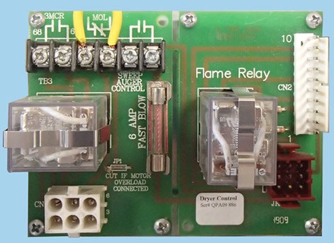
The Flame Control Board and the Auxiliary Unload Control Board are contained on one printed circuit board assembly. All purge timing, ignition timing, and pilot flame control are maintained by the QUANTUM® through this interface assembly. In addition to auxiliary equipment control, this Board also controls the sweep auger separately from the discharge auger on MEYER® Dryers. In the same manner, it controls the metering augers separately from the discharge auger on the 1200 Low- Profile models. This is done to ensure that the discharge auger continues to run for a preset time after the sweep auger stops, to “flush” the discharge auger, so that during startup, the augers are not under load with grain buildup.
This is for a dry contact closure only.
DO NOT FEED AC power back into this input!
1
2
3
4
4
Input Module Card
The Input Module Card converts the 120VAC signals from the Dryer, down to 5VDC so that the Slave CPU Board can process the information. This conversion is done through optical isolation to prevent damage to the slave board in the event of a power surge or high voltage transient. The Modules also have a means of providing a visual indication of the status of its input via a red LED located on the top of the Board. This is useful for troubleshooting the system and for initial check-out of the Dryer.
Each Module contains six (6) individual inputs. The QUANTUM® system requires four (4) of these Module Cards, so 24 items total can be monitored.
Output Module Card
The Output Module Card converts 5VDC signals from the Slave Board to 120VAC so that control of a power device can be accomplished. This conversion is done through optical isolation to prevent damage to the Slave Board in the event of a power surge or high voltage transient. The Modules also have a means of providing a visual indication of the status of its output via a green LED located on the top of the Board. This is useful for troubleshooting the system and for initial check-out of the Dryer. Each module contains six (6) individual outputs. The QUANTUM® system requires four (4) of these Module Cards, so 24 devices total can be controlled.

1
3

2
3
Input Module Card
The Input Module Card converts the 120VAC signals from the Dryer, down to 5VDC so that the Slave CPU Board can process the information. This conversion is done through optical isolation to prevent damage to the slave board in the event of a power surge or high voltage transient. The Modules also have a means of providing a visual indication of the status of its input via a red LED located on the top of the Board. This is useful for troubleshooting the system and for initial check-out of the Dryer.
Each Module contains six (6) individual inputs. The QUANTUM® system requires four (4) of these Module Cards, so 24 items total can be monitored.
Output Module Card
The Output Module Card converts 5VDC signals from the Slave Board to 120VAC so that control of a power device can be accomplished. This conversion is done through optical isolation to prevent damage to the Slave Board in the event of a power surge or high voltage transient. The Modules also have a means of providing a visual indication of the status of its output via a green LED located on the top of the Board. This is useful for troubleshooting the system and for initial check-out of the Dryer. Each module contains six (6) individual outputs. The QUANTUM® system requires four (4) of these Module Cards, so 24 devices total can be controlled.

1
3

2
3

Slave CPU Board
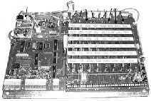
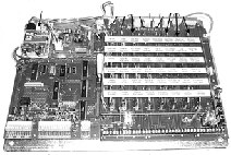
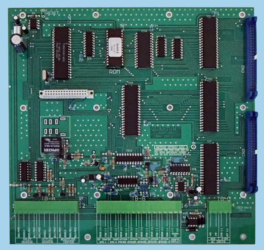
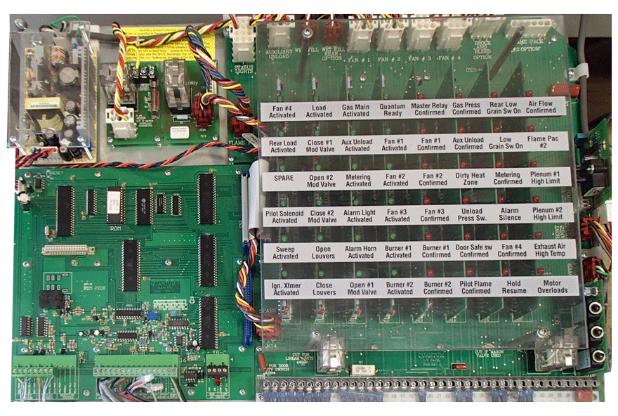
The Slave CPU Board is the "brains" of the Dryer Control Panel. It monitors all aspects of the drying process and activates all devices on the Dryer (Fans, Burners, load Motors, etc.). The Slave Board only does what the Master Control Unit tells it to do. In essence, the SLAVE keeps track of all details and reports this information to the Master. The Master then tells the Slave what adjustments to make and how much. The SLAVE carries out the instructions. All wiring connections for devices terminating outside the Panel box are made through removable type screw terminal blocks for easy hookup and troubleshooting.

1
2
3
4
5
6
7
8

Input/Output (I/O) Carrier Board (AC Power Interconnections)
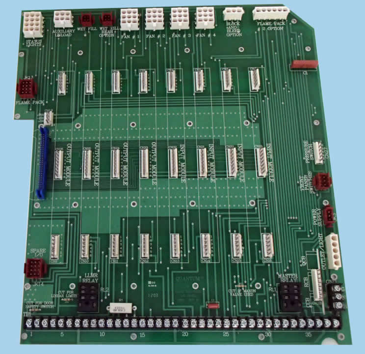
The I/O Carrier Board provides all the AC power interconnections between the Input and Output Cards, to and from the Dryer.
The I/O Carrier Board also provides all the low-voltage connections from the Slave Board to the Input and Output Cards. All connections for devices mounted within the Panel box are brought out to "plug in" type connectors located on the top and right sides of the I/O Carrier Board. All connections for devices which are mounted on the Dryer itself are brought out to a screw terminal block located on the bottom of the I/ O Carrier Board. All connection points are marked for easy identification.
1
2
3
4

Circuit Breaker Card
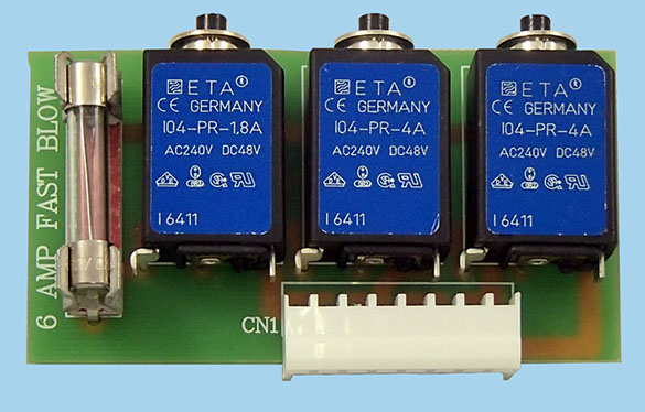
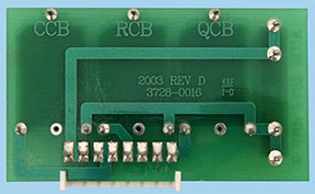
The Circuit Breaker Card provides overload and short-circuit protection for the three major circuits contained on the Dryer Control Panel.
- CCB or Control Circuit Breaker for the 120vac components;
- RCB or Remote Circuit Breaker for the QUANTUM® Monitor;
- QCB or QUANTUM® Circuit Breaker for the Slave CPU.
Overload conditions are protected by means of resettable circuit breakers, while an instantaneous short circuit is protected by means of a replaceable fuse. The entire assembly is built with a "pluggable" connector for easy field replacement. The assembly is located on the lower right-hand side of the I/O Carrier Board. The Circuit Breaker Card should be one of the first things checked when the Dryer Panel is dead.
1
2
3
x
Copyright © 2014-2016 CTB, Inc. All rights reserved BLV0216