SQ08-SQ40 Mechanical Installation Manual

Auxiliary Starter Control Connection
Factory-Installed Auxiliary Starter Units: Dryers ordered with the optional auxiliary starter unit have been wired at the factory. Verify that Motor sizes to be used match the sizes labeled on the starters within the auxiliary starter enclosure.
You will need wiring drawing Part No. 3724-00016A for Auxiliary Motor Starter wiring information. Click schematic at right to see a Zoom and Pan drawing of Part No. 3724-00016A.
IMPORTANT! Different circuit breakers, contractors, and/or overload relays may be needed if sizes do not match.
Connect the auxiliary Motor power wires directly to the correct overload relay block below the Starter. Start the Motors and check for correct rotation. Single-phase Motors must be rewired at the Motor junction box to change rotation. Three-phase Motors can be reversed by exchanging any two (2) of the three (3) Motor power wires.
Field-Installed Auxiliary Conveyor Starters
Consult a SUPERB® serviceman or a qualified electrician in selecting the correct Motor Starter for auxiliary conveyors.
For automatic sequencing with the Dryer, auxiliary conveyor starters supplied by the customer should be wired according to Schematic 3724-00016A in the back of the SQ Dryer Owner/Operator Manual MFH1932.
Load Auger Motor starter auxiliary contact wire terminals 66 and 67, and unload auger motor starter auxiliary contact wire terminals 68 and 69, provide switching action, not power, for the auxiliary motor starter coils. 115V coil power may be supplied from an external source or from the Dryer terminal strip to terminal contacts.
IMPORTANT! A tag or decal should be placed on the Control Panel stating that “This Panel has more than one source of power.”
Click Schematic to view a
Zoom and Pan drawing on screen
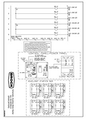
115V Auxiliary Starter Coils,
Single- and Three-Phase
Schematic 3724-00016A
Typical example of 115V auxiliary starter control circuit with overload relay interlock for one auxiliary load motor (M3) and two auxiliary Unload Motors (M1 and M2).
For more details see
Mechanical Installations Manual MHF1956F or Owner/Operator Manual MFH1932
Copyright © 2014-2016 CTB, Inc. All rights reserved BL0815