SQ08-SQ40 Mechanical Installation Manual
IMPORTANT!


The intent of this Manual is to help you follow step-by-step instructions for identification and installation of the BROCK® SUPERB® SQ Series Dryer.
Definition of Terms and Pictures
The Planning Symbol at left is used in areas where planning needs to take place before assembly and/or installation continue.
- “Horizontal,” “vertical,” “bottom,” and “top” refer to the Dryer as it is standing.
- The “front” (end) of the Dryer is the end with the Plumbing, Controls and Fan. The “rear” has the Plenum Access Door. See Below
- “Dryer/Equipment Disconnect” (noun): lever/handle located on the outside of the Electrical Power Cabinet, on the left-hand door or between the doors on the center post. Turns power ON/OFF to the Dryer.
- “Service Disconnect” (noun): sometimes located away from the Dryer in an electrical room on the facility. Turns power ON/OFF from the outside power service provider. Depending on local codes, it is the responsibility of the Service Provider and/or Owner to clearly mark the Service Disconnect and apply SAFETY Decals for dangers within.
- For SAFETY Decals click Safety on Index page.
Measurements
The symbols ('') equals inches and (') equals feet in English measurements. Metric measurements are shown in millimeters and square brackets following the English measurement. For example: 15' [4 572] 90' [27 432]
('') in inches (') ft feet A amps or amperes
FLA full load amps V volts sqft square feet
Ph phase
Identification of Parts and Hardware
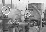
Guards/Covers have been removed in some photos for illustrative purposes only.
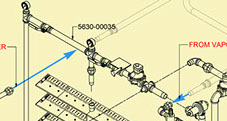
Diagrams are provided throughout this Manual to identify Parts used in that application. Parts and basic components are identified in Figures and their accompanying Tables as “Items” with a black number in white circle. See Below. Names for some components which have BROCK® Part Numbers have been capitalized within headings and body copy throughout this Manual to call attention to them.
Dimensions and lengths are noted with a brown circle on a line, then identified with numeric values in a Figure Table.
Dryer Orientation, Top View
Rear
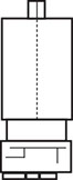
4
Front


MORE INFORMATION

This symbol represents a CLICKABLE Item Number.
Click or Touch the Item Number to view a detailed Drawing.

Click or Touch the Blue Balloon to view
a Detailed Description and Part Number.
4
5
6
x
1
2
3
4
1
2
3
Copyright © 2014-2016 CTB, Inc. All rights reserved BL0815