SQ08-SQ40 Mechanical Installation Manual

Auxiliary Conveyor Connection
Wet Conveyor capacity required for ''catch up'' capacity on powered Garner Bins; Dryeration capacity is approximately 30-40% higher than standard; Dry Conveyor capacity is based on emergency unload requirement plus conveyor manufacturer over-ratings.
IMPORTANT! Review and follow the “Electrical Connection/Disconnection Procedures for Dryer Testing” below, OSHA Lockout/Tagout regulation 1910.33(b)(2) through 1910.333(c)(2), and the “Manufacturer’s Recommended Minimum Lockout/Tagout Energy Control Procedures” see main menu in this Manual.
1. Read “Auxiliary Starter Control Connection” in the following section before wiring auxiliary Load and Unload Conveyors (Augers). You will need wiring drawing Part No. 3724-00052 (click schematic for a Zoom and Pan drawing) for the AC Drive. It is located in the back of this Manual and the Controller Manual:
2. If the Dryer is equipped with a factory-installed auxiliary Starter Unit, check for proper Motor voltage and horsepower ratings. Connect the Auxiliary Motor wires directly to the connect overload relay block below the contactor. In all cases, a separate auxiliary Starter Disconnect will be factory-mounted beside the Main Dryer Disconnect, and will tap into the service feeder wires powering the main Disconnect. If magnetic starters for Auxiliary Conveyors are supplied by the customer, the power wiring to the starters must be supplied from outside the Dryer to an auxiliary disconnect circuit breaker.
3. Terminal sets 66-67 and 68-69 can provide only switching action, not power, for auxiliary load and Unload Motor starter coils, respectively. (U.S. only) 115-volt control power (Auxiliary Starter Control Connection, Method I, see main menu) may be supplied from an external source or from the terminal strip to the terminal contacts; the voltage depends on the individual starter coil rating. If an external power source is used, install a tag or decal on the Control Panel stating that “This Panel has more than one source of power.”
4. Auxiliary conveyors must be installed so that they are not supported by the Dryer.
5. Install the Load Hopper so that the Slide Adjustment Bolt is on the side of the hopper away from the Dryer.
6 Auxiliary conveyor capacity for loading and unloading should be sized to meet maximum Dryer handling requirements if feasible. For pneumatic conveyors, the recommended rated capacity is closer to the Dryer rated capacity to keep system costs reduced.
7. When gravity bins are used, adjust the grain hopper Slide to regulate flow and eliminate Motor overload. Grain flow should be set so that the Load Motor amperage goes no higher than full-load amperage. The highest Motor load occurs at the end of the cycle.
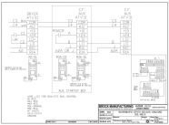
Schematic 3724-00052
(AC Drive Wiring)
For more details see
Mechanical Installations Manual MHF1956F or Owner/Operator Manual MFH1932
Copyright © 2014-2016 CTB, Inc. All rights reserved BL0815