SQ08—SQ40 2015 Dryer — Owner/Operator Manual
BASO Flame Sensor Switch
and Thermocouple
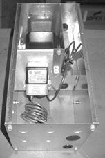
The BASO thermocouple sensor is mounted in an adjustable sleeve at the end of the Burner pilot baffle plate with its tip extending into the pilot flame. The other end of the thermocouple is connected to the BASO Switch inside the Burner Ignition Transformer Box. In operation, the thermocouple is heated and sends a millivolt (mv) signal to the BASO Switch which activates an internal relay.
To see the thermocouple signal strength, a millivolt meter is supplied with one lead grounded to the BASO SW and the other lead connected to a terminal inside the BASO Switch just opposite the thermocouple attachment point (the thermocouple must be connected to the BASO Switch). An unheated thermocouple will have an output signal of 0mv. As the thermocouple is heated, the BASO Switch relay should activate at approximately 9mv and drop out at 2-3mv. (The meter needle should “jump” when the internal relay switches.) The desired output range is 18-21mv. A lower signal causes marginal operation; a higher signal reduces the life of the thermocouple.
The thermocouple can be observed through the Plenum Access Door at the rear of the Dryer. In the desired range of 18-21mv, the tip of the thermocouple should have a dull red glow. If no color is visible, the mv signal is usually low (below 18mv). If a bright red color is observed, the mv signal is usually high (23-27mv).
If the thermocouple signal needs to be adjusted, use the millivolt meter. If the meter signal is low (such as 1-13mv) or no color change is observed, follow these steps to increase the signal: (1) Check the BASO thermocouple for a loose connection at the BASO Switch junction, (2) Move the thermocouple tip in the burner pilot baffle sleeve farther into the flame and tighten the lock collar set screw, or (3) adjust the pilot regulator to heat the thermocouple more (if increasing the gas pressure doesn’t increase signal, try decreasing the pressure). For a high signal or a “bright or cherry red” tip: (1) Reduce the amount of thermocouple exposure or (2) Adjust the pilot flame length with the pilot regulator to change the color to a “dull red” and/or the signal to 18-21 millivolts. If the millivolt reading (and color) are close to the “ideal” range of 18-21 millivolts, turn on the main burner and observe the thermocouple conditions. The full burner flame compresses the pilot flame and sometimes changes the thermocouple signal to a desirable level. If no signal or a low signal is observed under all adjustment conditions, the thermocouple is probably weak and should be replaced.
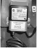
Flame Relay
Flame Sensor Switch is also called the BASO, located in the Burner Ignition Transformer Box next to the Burner Access Door on the top of the Dryer. A BASO flame switch with a BASO thermocouple serves as the pilot flame sensor. The BASO Switch normally closes within 10-20 seconds after the pilot flame is established, energizing the Flame Relay. If the pilot flame goes out or weakens (to the point the thermocouple signal is inadequate), the BASO will open, instantly de-energizing the Flame Relay.
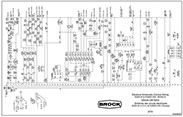
Control wiring for the SPECTRUM®/QUANTUM® Flame Relay, Schematic diagram 3724-00125, located in the back of the QUANTUM® Controller Manual Supplement, MFH1978; the SPECTRUM® Controller Manual Supplement, MFH1977; and the SQ Owner/Operator Manual MFH1932
BASO Flame Sensor Switch
Schematic 3724-00125 (SPECTRUM®/QUANTUM® Flame Relay)
Click to view a Zoom and Pan drawing

1
2
3
Copyright © 2014-2016 CTB, Inc. All rights reserved BLV0915