SQ08—SQ40 2015 Dryer — Owner/Operator Manual

Checkout and Adjustments
1. Make sure all annual maintenance steps have been followed (see Preventive Maintenance, See Main Menu, especially lubrication and cleaning.
2. Make sure all removable Doors, Guards and Covers are in place.
3. Be sure the Unload area is clean and Covers are secured.
Do not step on and/or bend the perforated inner grain panel sheets when the Dryer is empty.
4. Fill the Hopper Control Gate: Initially set to 3'' - 5'' [7.6 - 12.7 cm] clearance at the intake side. Final Gate clearance should be set while filling, so grain covers the lower edges of the Plate to provide a seal to keep dust and fines from blowing out.
5. Wet and Dry Auxiliary Conveyors: Check that they are correctly oriented and operational.
6. Modulating Valve: Check that linkage is tight and in alignment.
7. Inlet Gas Valve: The manual Shutoff Valve located near the Inlet connection on both LP and Natural Gas plumbing trains. The Inlet Gas Valve(s) should be turned OFF any time the Dryer is not operating. U.S. only: If the Dryer is equipped with the dual LP-NAT plumbing option, make sure proper orifices are installed per gas type. After verifying both Inlet Gas Valves are closed, open the manual Inlet Gas Valve for the desired fuel.
8. Service Light: To keep electrical control circuit components warm, turn on at least one hour prior to daily startup (or leave on overnight) if the outside temperature is below 32 degrees F [0 degrees C]. Do not use this light in the daytime if the temperature is above freezing (32 degrees F/0 degrees C).
Failure to follow the following directions may result in an unsafe situation.
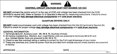
9. If the Dryer is wired for three-phase power, check the control circuit voltage before starting the Dryer, to verify that it is within a 110V to 125V range. Follow instructions on the bilingual Circuit Breaker Card shown at right (5542-00001, ships loose):
• Install the card with the circuit breakers facing toward the I/O Panel. make sure that the fuse is installed and that it is rated at 6 amps.
• Make sure that the connector on the circuit breaker is lined up with the male end on t he I/O Panel.
• Firmly press the card straight into the connector until it is secure and in place. Failure to press the card straight may cause the male connector to break on the board.
10. Check rotation of Motors. Click Link Below
11. With the fuel in the Plumbing Train under pressure, check all fittings for leaks with a liquid soap solution, especially at unions.
12. After the first four to six hours of operation, re-tension Motor Belts as per instructions in the section Preventive Maintenance. See Main Menu.
GO TO MOTOR ROTATION
ENGLISH
ESPAÑOL


Circuit Breaker Card
Copyright © 2014-2016 CTB, Inc. All rights reserved BLV0915