SQ08-SQ40 Mechanical Installation Manual
A
1
2
3
5
6
7
8
10
For this operation, a 1/2'' impact with a 1 1/4'' impact socket works best.
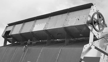
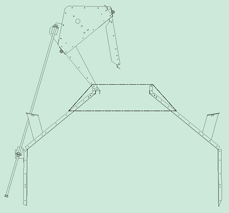
The Garner Bin is the wet grain holding bin at the top of the grain columns. It provides a surge, or working volume of wet grain so the Plenum air seal is not broken on Dryers with leveling augers that operate intermittently. The Garner Bin holds approximately 4.5 bushels per foot of Dryer length, providing 10 to 30 minutes’ drying volume (5 to 15 percent moisture removal). The Garner Bin can be folded down for shipping.

REAR
TOP VIEWS
LEFT

RIGHT
FRONT
Standard Load/Unload:
Garner Bin Located on LEFT
Reverse Load:
Garner Bin Located on RIGHT
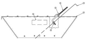
If more than one Lifting Rod (may also be called an Erection Screw) is used on the Dryer, two (2) impact wrenches are better. To avoid bending the Garner Bin, lift it as evenly as possible. Take your time and be safe. Lubricate the Garner Bin Lifting Rod prior to use. The Garner Bin can be lifted into assembly position with the provided Lifting Rod assembly. An impact or heavy-duty drill are best suited for driving the assembly.
1
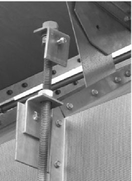
Lifting Rod Assembly
Garner Bin Lifting Rod

9
1
2
3
3
3
4
5
6
7
8
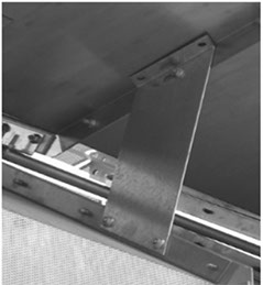
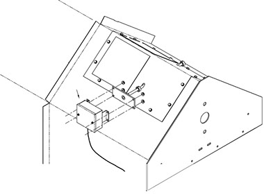
Garner Bin fully extended and attached to the skin flange.
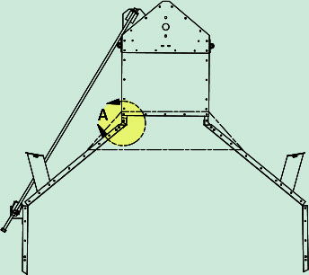
Detail A
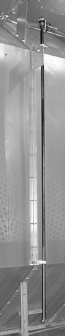
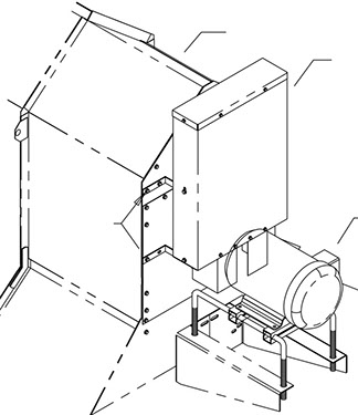
The Top Grain Level Switch (or TGL, Item 1) is a mercury switch connected to a paddle (Item 2) that is hanging vertically beside the wet fill auger. When the paddle is rotated counterclockwise either by hand or by grain flow, the Switch contacts close, starting the WET FILL timer.
Check the TGL Paddle for free rotation.
1
2
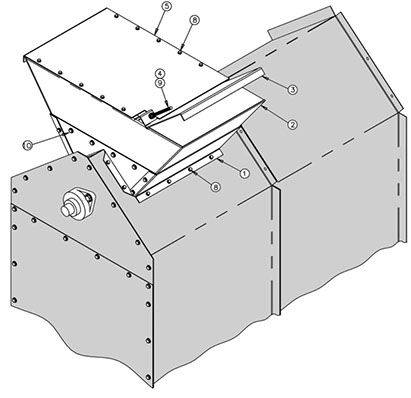
Sub assemble Items 2, 3, 4, 5, and 6 before installing the Hopper Extension on the Dryer.

1
2
4
5
7
7
8
9
3

8
8
4
6
3
2
Garner Bin Extension Assembly

A
1
2
3
4

1
2

Garner Bin Assembly
1. Unbolt the Garner Bin from the top edge* (see Detail B) of all the shipping braces. This will require two (2) 1/2'' wrenches or sockets. There are times when the shipping brace will not release from the Garner Bin. Do not discard the hardware as it should be reinstalled when the lifting operation is completed. Apply a slight amount of upward pressure using the Lifting Rod.
Locate the lifting mount which is attached to the Garner Bin. It should be on the same rib as the lift bolt. Remove the shipping brace, for access, (do not discard) and reinstall it when the lifting operation is complete. The bolt used to attach the Lifting Rod to the lift bracket is a 3/8'' Bolt with a self-locking Nut.
2. Rotate the Garner Bin Lifting Rod into position. Secure the lifting brackets together with the 3/8'' Lock Nut and 3/8'' Bolt. Finger-tighten snugly
3. Lift the Garner Bin into position by turning the Lifting Rod clockwise. For Dryers with more than one Lifting Rod, make sure that the Garner Bin rises fairly level. For best results, alternate between Lifting Rod assemblies, raising 5'' or 6'' [12.7 or 15.2 cm] at a time at each location. Lift until the skin flanges are in alignment with the holes in the gussets on the Upper Basket on the opposite side of the Lifting Rod.
As you install the Lifting Rod to the bracket, be sure the pivot bolt is not too tight. The Lifting Rod must be allowed to pivot freely.
4. To install the galvanized End Panels (approx. 21'' x 27''): Remove the lower 5/16'' x 3/4'' Bolts on each end of the Garner Bin near the upper triangular bulkhead. These End Panels are to be installed on the outside of the upper triangular bulkhead and the upper galvanized bulkhead using 5/16 x 3/4'' Self-tapping Screws along the top, sides, and inner four (4) holes along the bottom edge. Leave all these fasteners loose until the 5/16'' x 3/4'' Bolts and Nuts can be installed in the outer four holes above the Garner Bin Pivot Bolts (at the galvanized upper bulkhead). Tighten completely.
If the Dryer is set for REVERSE load, the Garner Bin will lay on the RIGHT side of the Dryer.
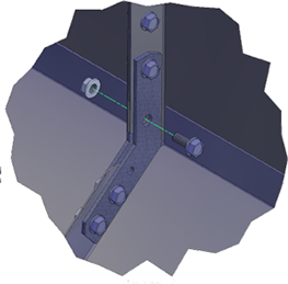
5. Install the 5/16 x 3/4'' Whiz Lock Bolts connecting the gussets to the Garner Bin (both sides) and into the open hole in the skin flanges.
6. The Top Grain Level Switch Assembly is located at the end OPPOSITE the fill end of the Garner Bin. Check the Paddle for free rotation.
For Auxiliary Conveyor connections, see link below in Electrical Installation.
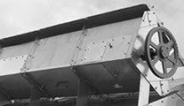
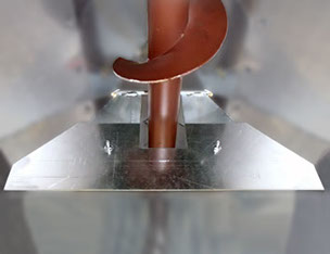
7. On the opening over the load Auger (Picture A), install the Fill Hopper Assembly with 1/4 x 1/2'' Sheet Metal Screws to the opposite end of the Garner Bin. It can be located at either end of the Dryer.
The Fill Hopper Control Slide Plate is an inclined slide plate that is adjusted to provide a grain feed opening adequate for the volume being conveyed, while keeping the grain column weight from loading down the end of the auger. It maintains a seal in gravity systems and keeps the auger from throwing grain out of the Hopper on both conveyor and gravity-filled systems. Install the Slide Gate and Lid.
8. Check that the Auger turns freely by hand. Install the Load Auger Belts, making sure they are aligned. Tighten the Belts. Install the Belt Guard.
9. The Lifting Rod Assembly can be removed, or can remain on the Dryer for future Garner Bin fold-down (for storage/ transport).
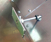
10. Once the Garner Bin has been erected, secure the Top Grain Level Switch “Can” to the Paddle Weldment as shown, using the Nuts and Bolts
provided.
11. Install the Drag Extension option (shipped loose).
AUX Conveyor Connections
Copyright © 2014-2016 CTB, Inc. All rights reserved BL0815